Summary:
When a TEC system transitions from heating to cooling, energy can be fed back into the power supply, causing short voltage spikes on the input. If not managed, this can trigger instability, shutdowns, or component stress in high-power or dynamic systems. A brake chopper connected in parallel clamps the voltage and dissipates excess energy as heat, ensuring stable operation.
Key Takeaways:
- Direction changes (heating → cooling) can cause regenerative voltage spikes
- These spikes can destabilize or damage power supplies in dynamic systems
- A brake chopper clamps voltage and dissipates excess energy
- Result: stable operation under fast temperature transients
In high‑power TEC applications, rapid transitions between heating and cooling can lead to energy being fed back into the power supply. In practice, this appears as short‑term increases in voltage at the input of the TEC controller. This problem usually only occurs with high-power devices, such as the TEC-1163 and the TEC-1167.
This increase in voltage can lead to a shutdown of the entire system. In rare worst-case scenarios, damage to the power supply is also possible. This risk is significantly increased by low-cost power supplies without suitable protection mechanisms.
A brake chopper limits these effects by dissipating excess energy in a controlled manner.
Feed-in Behavior in TEC Systems
In high‑power applications, switching between heating and cooling can generate electrical energy. This energy is fed back into the power supply through the TEC controller, causing the DC input voltage to rise.
In the measured setup with a nominal 24 V supply, the input voltage of the TEC controller increased noticeably when switching from heating to cooling (see Measurement Setup).
Brake Chopper as a Countermeasure
A brake chopper is an external component connected in parallel with the supply of the TEC controller. It becomes effective when an adjustable activation voltage is exceeded and dissipates the fed‑back energy as heat.
Integration in Existing Systems
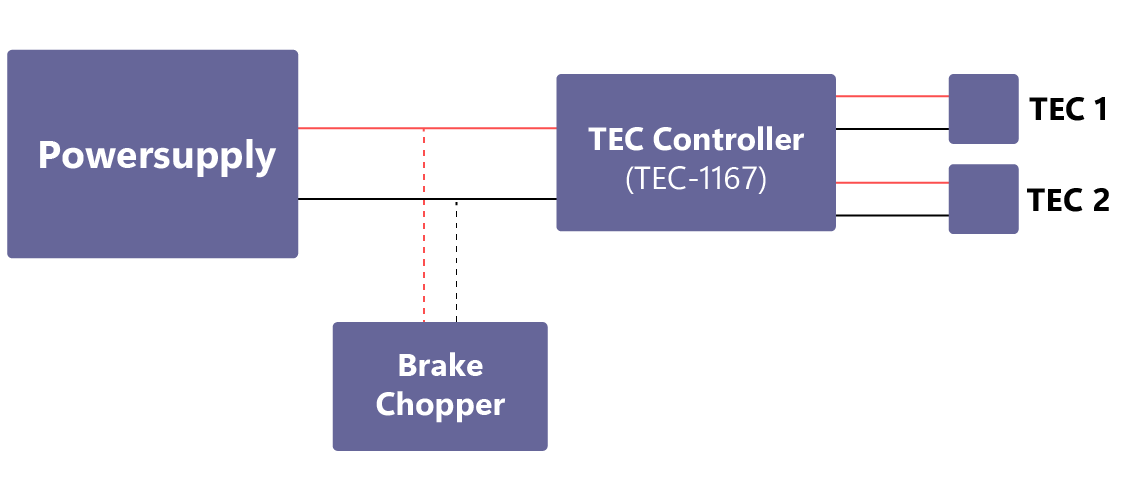
In the configuration shown (see Figure 1), integration is implemented exclusively at the hardware level. The power supply is connected in parallel, and the activation voltage can be adjusted as needed. No modifications to the firmware or the control loop are required.
Measurement Setup
- Power Supply: Elektro-Automatik EA-PS 9150-19
- TEC Controller: Meerstetter TEC-1167, S/N 542
- Chopper: Nanotec BC72-50
- TEC (Peltier element): TEC1-12705
Practical Benefits
In practice, this approach offers several advantages:
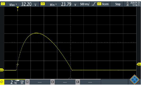
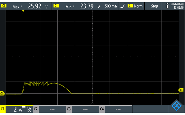
- Reduced stress on the TEC controller and the power supply (compare Figure 2 and 3)
- Fewer unplanned shutdowns during dynamic operation
- More stable behavior during rapid temperature transitions
- Less need to oversize the power supply
The difference in supply voltage behaviour with and without a brake chopper is illustrated by Figures 2 and 3:
Typical Applications
Brake choppers are originally used primarily in drive technology, for example with motor controllers. When a motor is decelerated, mechanical energy is converted into electrical energy that must be dissipated in a controlled manner.
A similar effect occurs with Peltier elements: when switching between heating and cooling, electrical energy can be fed back into the power supply. In such cases, a brake chopper can be used to dissipate the resulting energy in a controlled way.
Typical application scenarios include:
- High power TEC systems
- Applications with rapid load or operating transitions
- Large temperature gradients
- Systems with sensitive or power limited power supplies
Conclusion
In high‑power applications, feed‑back during transitions between heating and cooling can lead to an increase in the DC input voltage. A brake chopper reduces the voltage peak by dissipating the excess energy as heat.
Next steps
- Read
the Application Note Brake Chopper (PDF)
Find detailed measurements and setup information. - Explore our TEC Controllers
Find suitable TEC controllers for dynamic and high‑power applications.